Tetra Field
Gabriel Dunne
2014
laser-cut plywood, grasshopper, touchdesigner, python
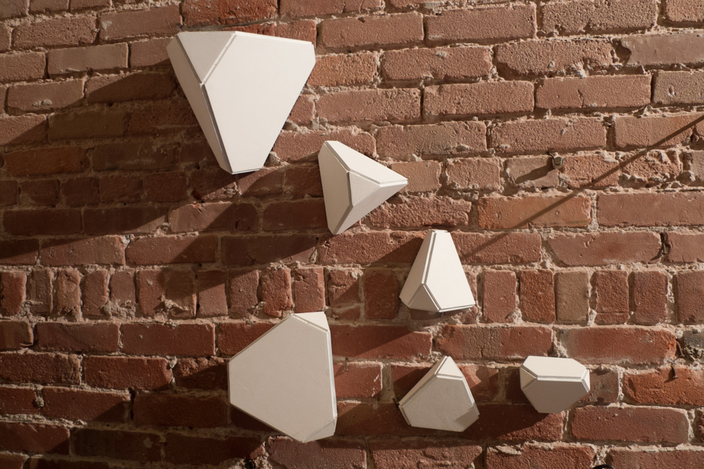
A series of algorhythmically generated projection-mapped truncated tetrahedrons laser-cut from 10mm ply. All vary in size, orientation, truncation, and all have a boolean intersection with the wall as if each object is embedded within it. After manual assembly, the generated geometry is utilized as a base for projection mapping.
This project was realized as an experiment in creating a fast, efficient solution for a tightly-linked fabrication and projection-mapping workflow. Sculptural form, build plans, material cut files, and projected graphics are all generated from software and parametrically linked.
Software
Fabrication Tools
- 4x2 LaserSaur Laser Cutter
Materials
- 10mm Plywood
- Cyanoacrylate Super Glue
- Neodynimum Magnets
- Angle Brackets
- Gap-filling primer
- White Silicon Caulk
- Gaffers Tape
- L-Brackets
Installation Hardware
- LCD Projector
- PC
Design & Fabrication
Geometry was created in Grasshopper/Rhino via the gHowl LunchBox toolkit and GhPython.
Supports
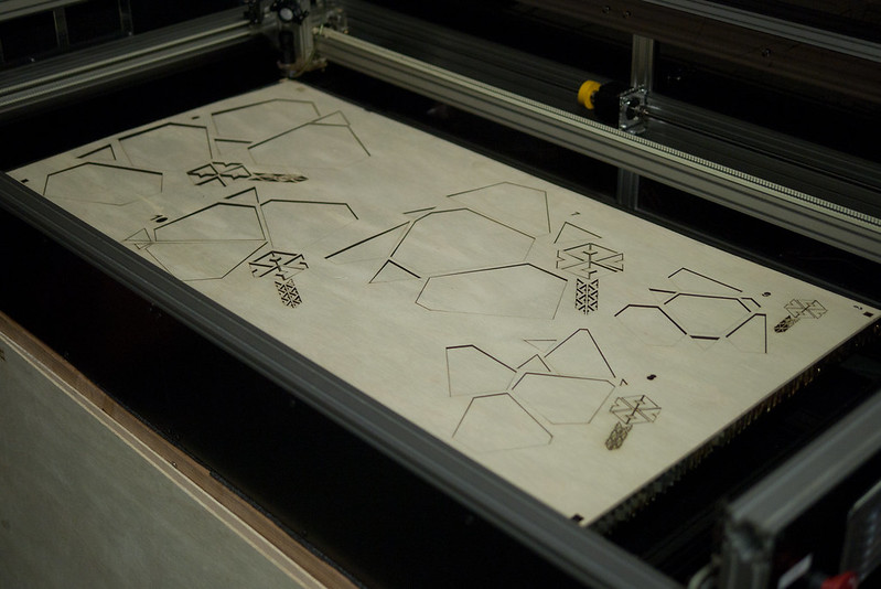
 Gometry and supports layed out for cutting.
Laser Cutting

Forms were cut with a LaserSaur laser cutter from sheets of lightweight, low-grade 10mm ply.

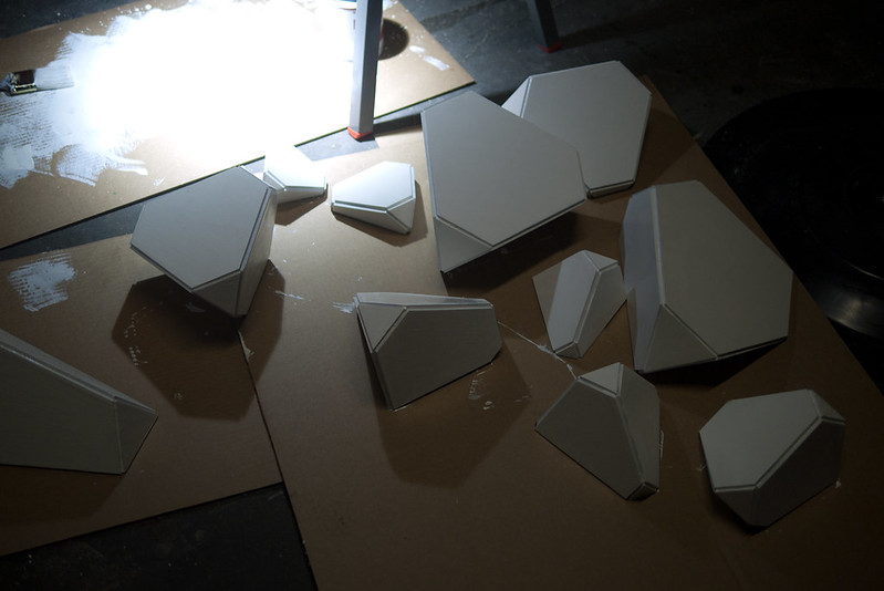
Panels are superglued together by hand. The interior support structure relies on two angle wedges, which are attached on the interior of the forms.

After glue-up multiple coats of white primer is applied. I did a light hand sanding of the laser-cut plywood edges, as the laser-braze is a tough surface to get paint to adhere to, and therefor coat well enough so it appears completely white. Grey would have looked nice and worked well.

Installation
Ultra strong neodynium magnets attracted to large-headed nails or screws into the wall were used as a mounting solution.

Projection Mapping
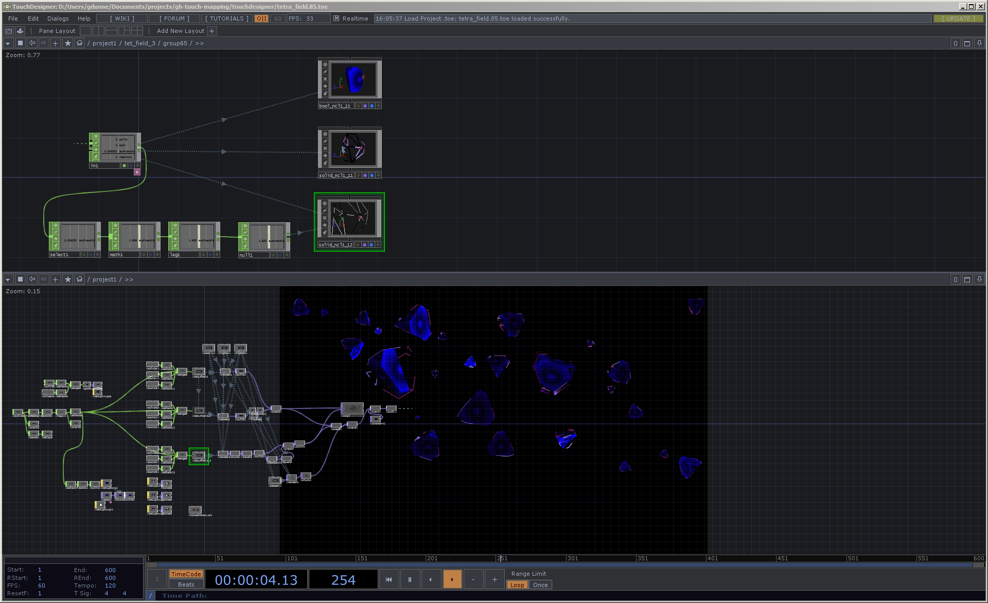
Geometry is piped into TouchDesigner via OSC
Once geometry is generated in TouchDesigner, the projected meshes can be aligned onto the sculpture.
Graphics
Shaders applied to the mesh faces. This installation was part of a group show, and I used the audio-input from the sound generated from Sasha’s Drum Piece.

Final Thoughts
Software
This project did not attempt to solve the task of of aligning projections to the physical objects. Because of their simple geometric shape, I had planned to first install them on a surface and register the projections manually. For future iterations, I’d am considering ideas that include embedded fiber-optics in the verticies that would be tracked with an IR camera for a precise, real-time alignment. A huge challenge involved in projection mapping objects is the sheer amount of time it takes to align projections, and creating a real-time mapping solution allows for articulated and or moving installations.
Fabrication
This iteration does not include a solution mitered corners, due to the physical tendancies of the laser cutter. However, the lack of mitres simplified the fabrication process considerably and was a benifit – as this design reveals a channel between faces that makes a perfect area highlight the polygon edge when mapping.